


Most problems with a lifeline installation do not appear on installation day. They appear months later, when someone asks for the installation certificate, when the inspector asks what the post is anchored to, or when the owner wants the logbook and nobody has it.
This guide walks through the full lifeline installation process: what to verify before going up on the roof, the horizontal and vertical installation procedure, the particulars of each surface type, and the documentation that closes out the job.
Before Installing: Project, Surface, and Applicable Standards
Before carrying out an installation, we need to be clear on these questions: what it will be anchored to, how much clearance there is below, and how many workers will use the system at the same time.
The reference standard is UNE-EN 795 for anchor devices (type B portable, type C horizontal flexible line, type D rigid rail) and UNE-EN 353 for vertical sliding fall arresters. If the system allows several simultaneous users, the reference is technical specification CEN/TS 16415. In Spain, RD 2177/2004 sets the conditions for temporary work at height and RD 1215/1997 for work equipment.
And a rule that saves headaches: the lifeline comes in when collective protection is not feasible. If the perimeter can be protected with a guardrail or net, that is the preferred solution. Personal protection comes later in the hierarchy of prevention, not before.
Roof Survey and Anchor Points
All of the arresting force ends up on the substrate. If the substrate fails, everything fails. That is why the installer must check on site:
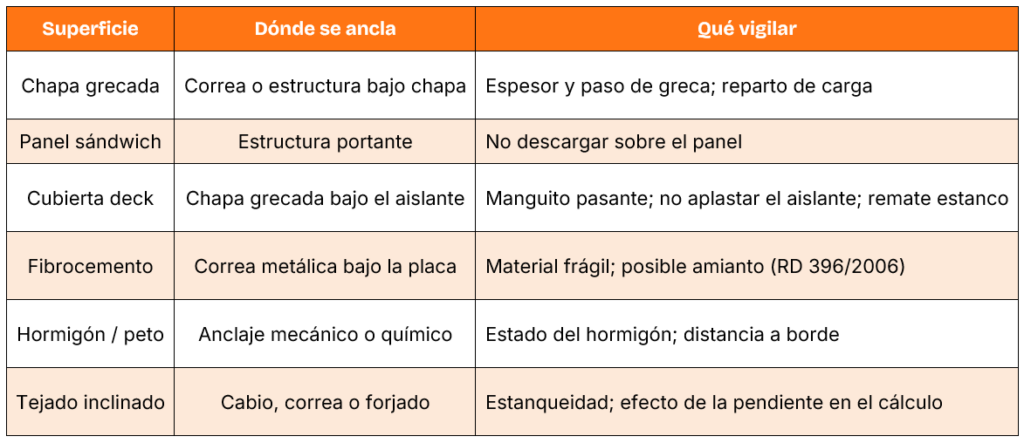
- The actual load-bearing element. Not the finish. On trapezoidal metal sheet, the purlin; on fiber cement, the structure under the sheet; on a deck roof, the sheet beneath the insulation; on a pitched roof, the rafter or the slab. The anchor is never fixed to the cladding material.
- Structural capacity of the point. The manufacturer’s manual does not settle this check: the project or the competent technician does. It is the data that backs you up later.
- Clearance below the work plane: this calculation determines whether the system can stop the fall in time, because under load the cable deflects (known as sag), and that deflection adds to the total fall distance. When there is not enough clearance to allow for this deflection, a cable cannot be used and a rigid rail must be used instead.
- Actual work path: the lifeline should not be designed as a simple straight line between two points, but must follow the actual maintenance route, including the path to the machine, the detour around the skylight, and access to the roof edge.
- Simultaneous users. the number of workers who will use the system at the same time directly affects its sizing, since designing for two workers is not the same as designing for four, and this affects both the system as a whole and each individual anchor.
- Roof access. you also need to resolve how the first worker gets onto the roof before the lifeline that will protect them is installed, which is solved with auxiliary equipment or a temporary protection system, and must be included in the work plan.
Tools and Components Needed for Installation
A well-designed system does not require many tools. Normally, a drill or impact driver, a torque wrench to tighten the bolts correctly, a tool for tensioning the cable, a tension gauge, a level, and some measuring equipment to mark positions is enough. On top of that, of course, comes the installer’s own protective equipment.
On the system side, the necessary components are: end, intermediate, and corner anchors, stainless steel cable or rail, energy absorber, tensioner with indicator, trolley or slider, hardware, identification plate, and logbook.
It is important to contact the manufacturer if a part is missing or damaged, because if the installer improvises a component without the manufacturer’s approval, the system is no longer under warranty and legal liability in the event of failure may fall on whoever improvised, not on the original manufacturer.
Installing a Horizontal Lifeline
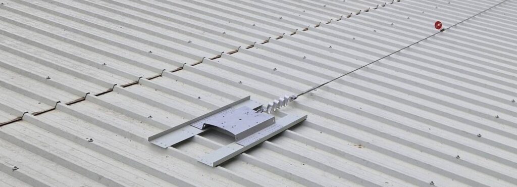
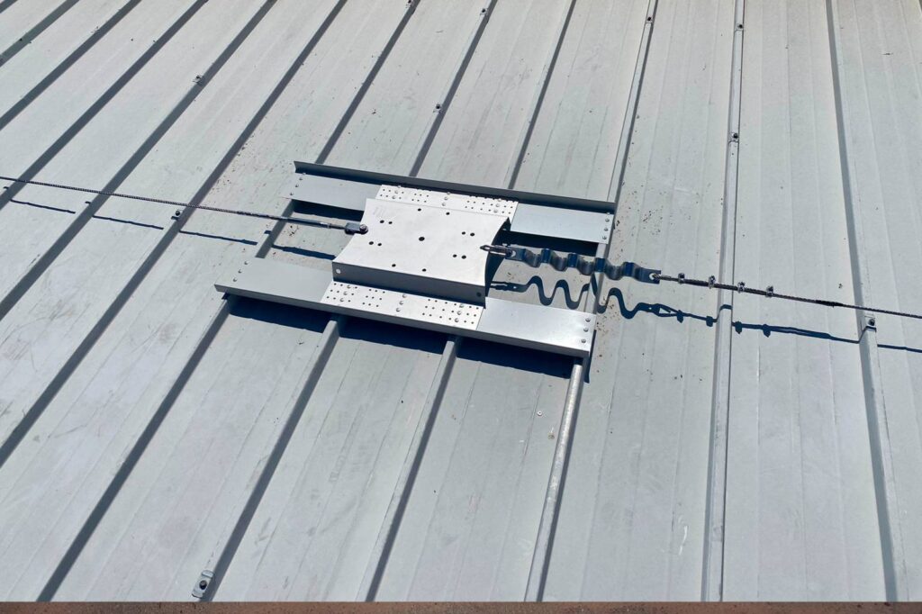
The horizontal lifeline is the most commonly installed type on roofs, as it consists of a cable tensioned between end posts, with continuous-pass intermediate anchors that allow the user to travel the entire route without disconnecting.
Installation Procedure on a Roof or Structure
- Layout. The route is marked on the roof following the work path and the load-bearing elements are located. The position of the anchors will depend on the structure; they are placed where it can actually support the load, regardless of appearance.
- Drilling and fastening the anchors. Fastening differs depending on the type of surface: on sheet metal, a self-drilling anchor into the purlin is used; on deck-type roofs, a through sleeve is used; on concrete, a mechanical or chemical anchor is used; and on fiber cement, a through bushing is installed down to the structure.
- Sealing the penetrations. On any waterproofed roof, each drilled hole is a point of water entry, so the finish must be done with the same material as the membrane.
- Assembling the line. The cable is passed through the intermediate anchors, the terminals are connected, and the energy absorber is installed.
- Tensioning. This is done with the tool and the gauge until reaching the value given in the manual, since it is not a matter of just tightening but a parameter that falls within a specific range.
- Verification and commissioning. Tightening torques, tension, slack, and free passage of the trolley are checked. Finally, the identification plate is placed and the logbook is opened.
Fastening End Anchors, Intermediate Anchors, and Tensioner
The three elements work differently, and it is worth being clear on this before planning the installation:
- End anchors: they take most of the load, so the substrate requires greater structural verification.
- Intermediate anchors: they support the cable and allow the trolley to pass continuously. The spacing is set by the manufacturer depending on the intended number of users.
- Tensioner and absorber: the tensioner includes the tension indicator, and the absorber limits the force transmitted to the user and the structure in the event of fall arrest.
How to Install a Temporary Horizontal Lifeline
The temporary horizontal lifeline is installed and removed during the same job, using a portable anchor (EN 795 Type B) on existing structural points, typically textile webbing with a ratchet tensioner.
Compared with the permanent version, with this type the anchor point must be checked before each use, it requires more clearance, and the expiration date stated by the manufacturer for the textile components must be taken into account.
Installing a Vertical Lifeline
The vertical lifeline protects the climb, which is precisely when the worker is most exposed, since they climb with both hands occupied and face a free fall from the very first rung.
Installation on Fixed Ladders and Access Routes
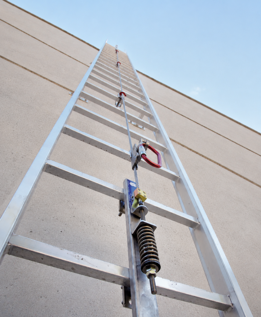
The system runs the full length of the ladder by means of an upper anchor, a lower anchor, intermediate guides fixed to the side rails, and an anchor line (tensioned cable or rail) with the sliding device that travels with the user.
The critical point of the installation is at the top, not the bottom: the exit at the top is the moment when the worker leaves the ladder, and where the system has to maintain the connection until the user is in a safe area, since a good share of climbing incidents occur during this transition.
It is also advisable to check that passage through hatches and intermediate platforms is continuous, because if the system forces the user to disconnect at any point along the route, that point becomes the failure.
When to Install a Vertical Lifeline
It is installed when the ladder does not have the appropriate safety cage for the height required by the regulations, or when there is any interference with the project.
We have to keep in mind that the safety cage is not a fall arrest system. It reduces the risk of tipping backward, but it does not arrest a fall. Adding a lifeline to a ladder with a cage is recommended and perfectly compatible.
Installing a Lifeline on a Roof
On a pitched roof, the problem is not the cable but reaching the structure without breaking the watertightness. The anchor passes through the finish and is fixed to the rafter, the purlin, or the slab, never to the roofing material.
The slope adds one more factor to consider, since it changes the fall trajectory and, with it, the load reaching the anchor and the stopping distance. A system designed for a flat roof is not suitable for a pitched roof; the necessary adjustments must be made.
Specifics by Roof Type
Certification of the Lifeline Installation
Here it is worth separating two things that are often confused:
- Product certification: it is provided by the manufacturer and certifies that the system has been designed and tested in accordance with the standard, and it takes the form of the declaration of conformity, the CE marking, and the test report.
- Installation certificate: it certifies that this system has been installed on this specific roof in accordance with the manufacturer’s manual and on a substrate with verified capacity. It is issued by the installer or the competent technician who supervises the installation.
Both documents are necessary, since one without the other certifies nothing. You can find details of our testing on the installation certificate page.
Cost and Documentation of the Installation Certificate
The certificate itself does not have a fixed price; what drives up the cost is having to find out whether the structure is safe when that information does not exist beforehand.
The documentation that must be left with the owner after installation:
- Declaration of conformity and CE marking of the system.
- Manufacturer’s test report.
- Installation and user manual.
- Installation certificate or record, showing the actual route as installed.
- Verification of the structural capacity of the anchor points.
- System logbook, with the inspection schedule.
- Identification plate installed on site: number of authorized users and date.
Installation Errors That Invalidate the System
Before carrying out the work, we must verify that a system is backed by its testing and keep these situations in mind:
- Mixing components from different manufacturers. The assembly is certified as a system, not piece by piece. An anchor from one brand with a trolley from another invalidates the test. This is not a commercial matter; it is governed by the laboratory report.
- Anchoring to the finish instead of the structure. This is the most frequent failure and the hardest to detect, since it is not visible until a fall has to be arrested.
- Exceeding the maximum anchor spacing set by the manual, even if it “holds.”
- Tensioning outside the range. Neither slack nor over-tensioned; the indicator is there to check this.
- Ignoring the clearance calculation. A system that stops the fall two meters below the floor is a system that does not work.
- Installing without checking the capacity of the substrate. If the project does not document it, you must request it in writing before installing.
- Commissioning without an identification plate or logbook.
Who Can Install and Certify a Lifeline
Installation must be carried out by personnel with specific training in work at height, following the manual of the system manufacturer, which specifies the minimum strength required of the anchor point, the permitted surfaces, the spacing between anchors, the tightening torque, and the maximum number of users.
What the manual does not specify is the structural capacity of the substrate. That verification is the responsibility of the project or the competent technician, and it should be obtained before installing, not afterward.
At Ypsos Safety we manufacture and test our products, delivering them with all the documentation an installer needs. If you need any additional documentation, do not hesitate to contact us for more information.
Frequently Asked Questions About How to Install a Lifeline
How should a lifeline be installed?
By following the manufacturer’s manual and on a substrate with verified structural capacity. The process begins before installation, by identifying the actual load-bearing element, calculating the clearance available below the work plane, defining the route according to the actual maintenance path, and determining how many users will be connected at the same time. Next, the layout is marked out, the end and intermediate anchors are fixed to the structure, each penetration is sealed if the roof is waterproofed, the line is assembled with its absorber, tensioned to the value given in the manual, and verified before commissioning. The job is completed with the identification plate in place and the logbook opened.
How much does it cost to install a lifeline?
It is not calculated per linear meter, even though that is the unit it is usually requested in. It varies depending on the number of anchor points, the type of substrate it is fixed to, the load-bearing element, and the number of simultaneous users. In addition, it depends on whether the structure is well documented, as well as commissioning.
Who should install a lifeline?
Personnel with specific training in work at height, following the system manufacturer’s manual. That manual sets the minimum strength of the anchor point, the permitted surfaces, the spacing between anchors, and the tightening torque.